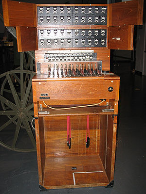
Switchboard F and F
| Switchboard F&F | |
|---|---|
 A F&F in a 40 line configuration | |
| Specifications | |
| Weight | 164 lbs (20 line) 193 lbs (40 line) 222 lbs (60 line) |
| Length | 20" |
| Width | 21.5" |
| Height | 42.5" (20 line) 48.5" (40 line) 54.5" (60 line) |
The switchboard is of the magneto type but facilities are provided for connection of five lines per position to central battery (C.B.), central battery signalling (C.B.S.) or automatic telephone systems. Direct connections are therefor possible to Army or civilian exchanges.
The Mk. 1 and Mk 1* switchboards are identical in design except for the method of connecting the external lines, and the Mk. 2 switchboard differs from the Mk. I* in the unit to which external exchange lines are connected. The Switchboards F and F, Mk. I* and Mk. 2 are arranged to use cables terminating in connection strips while the Switchboard F and F, Mk. I is provided with line terminals.[1]
The switchboard is erected from separate units, the number varying according to the number of subscribers' lines to be accommodated. Unit C is the key shelf which contains the cord and operator's circuits. Unit D forms the base of the switchboard when constructed and also serves as a case for carrying unit C during transport. Unit B is a 20 subscriber unit which is made up of four units A. Unit A is a five line terminal unit with additional night alarm and earth terminals.
Related Pages
- No related pages at this time


